 English



Views: 0 Author: Site Editor Publish Time: 29-08-2026 Origin: Site


High-pressure fluid systems do not tolerate guesswork. A mismatched thread type risks catastrophic blowouts, costly downtime, and severe equipment damage. Fluid power systems run on absolute precision. If a single seal fails, the entire machine abruptly stops. For procurement teams and engineers replacing components or designing system routing, correctly identifying the thread standard is the non-negotiable first step in parts evaluation. You cannot build a reliable machine on flawed or guessed connections. Every port requires careful attention to measurement detail.
This guide breaks down the precise methodology for measuring, evaluating, and specifying the exact hydraulic hose fitting required to ensure leak-free integration. You will learn how to protect your larger system architecture from preventable failures. We provide actionable steps to eliminate installation errors completely. Following these methods ensures you specify the right component for every high-pressure application.
Visual inspection is insufficient; precise specification requires calipers, a thread pitch gauge, and a seat angle gauge.
Understanding the sealing mechanism (tapered threads, O-rings, or metal-to-metal angled seats) is as critical as matching thread pitch.
Incompatible threads (e.g., mixing NPT and BSPT) will compromise the integrity of high-value **pump and valve parts** across the system.
System pressure, vibration levels, and existing port geometries should dictate your final specification framework.
Mismatched threads aren't just an assembly issue; they represent a severe safety and environmental hazard. High-pressure hydraulic fluid escaping from a ruptured connection acts like an invisible blade. It can cause severe injury to operators. Beyond safety, fluid leaks create environmental compliance nightmares. You face immediate cleanup mandates and potential regulatory fines. Connecting incompatible parts might feel secure during dry assembly. However, once you apply dynamic pressure, the compromised joint will inevitably fail.
You must understand the realities of cross-threading and stripped threads. When a technician forces incompatible standards together, they destroy the internal thread geometry. A classic example involves forcing a JIC 37° male end into an SAE 45° female port. The threads might initially engage, but the seat angles will never align. This creates severe micro-leaks. The fluid bypasses the deformed metal under pressure. Continuous vibration then widens these micro-leaks into major breaches. Relying on Teflon tape to mask these mismatched gaps guarantees a blowout.
A single failed fitting severely damages the broader hydraulic circuit. When fluid escapes through a micro-leak, the system experiences sudden pressure drops. This sudden loss of pressure can cavitate pumps instantly. Cavitation introduces air bubbles that aggressively erode internal metal surfaces. Furthermore, pressure drops starve critical control valves of necessary fluid force. This chain reaction threatens the operational lifespan of all interconnected Pump and Valve Parts. Fixing one cheap fitting becomes irrelevant if you destroy a highly engineered manifold in the process.
Accurate identification requires a systematic approach. You cannot "eyeball" thread types successfully. Follow these four specific measurement steps.
Step 1: Determine Parallel vs. Tapered. Start with a visual inspection. Look closely at the thread profile. Do the threads remain a constant diameter from top to bottom? If so, they are parallel (straight). Do they narrow as they reach the end? If so, they are tapered. You can confirm this using calipers. Measure the first thread, then measure the last thread. If the measurements differ, you have a tapered connection.
Step 2: Measure the Diameter. Use precision digital or dial calipers for this step. For male threads, measure the Outside Diameter (OD). Place the caliper jaws across the widest part of the thread crests. For female threads, measure the Inside Diameter (ID). Insert the caliper's internal measuring jaws into the port. Record this measurement precisely in both inches and millimeters.
Step 3: Measure the Thread Pitch. You need a specialized pitch gauge here. A pitch gauge features small metal blades with serrated edges. Press different blades into the threads until one fits perfectly without any gaps. Hold it up to a light source. If you see light shining through the teeth, try another blade. For Imperial fittings, this determines the Threads Per Inch (TPI). For Metric fittings, it measures the exact distance between thread crests in millimeters.
Step 4: Determine the Seat Angle. Parallel threads often rely on an angled seat to create a seal. Use a seat angle gauge to confirm this geometry. Slide the gauge into the connection until it rests flush against the sealing surface. You must check if the angle is 37°, 45°, or 60°. This angle dictates how the fitting creates a secure seal beyond just the interlocking threads.
Matching the thread pitch is only half the battle. You must perfectly match the sealing mechanism. Different industry standards utilize entirely different methods to contain high-pressure fluid. Let us evaluate the most common configurations you will encounter.
Hydraulic Thread Standard Sealing Comparison
Standard | Thread Geometry | Sealing Mechanism | Primary Characteristic |
|---|---|---|---|
NPT / NPTF | Tapered | Thread-to-thread deformation | Common in legacy equipment |
JIC 37° Flare | Parallel (Straight) | Metal-to-metal angled seat | High pressure adaptability |
ORFS (O-Ring Face Seal) | Parallel (Straight) | Compressed O-ring on flat face | Zero-leak high vibration resistance |
BSPP | Parallel (Straight) | Bonded seal or cutting ring | European standard compliance |
NPT features tapered threads. It creates a seal through mechanical deformation. As you tighten the connection, the male and female threads wedge tightly together. NPTF (Dryseal) improves upon this by crushing the thread crests into the roots. NPT is highly common in legacy US equipment. You can confidently specify an NPT thread fitting for standard pressure environments. However, recognize its limitations. Tapered threads struggle in high-vibration applications. Vibration causes them to back out and leak.
JIC uses parallel threads. It does not seal on the threads themselves. Instead, it seals via a 37° metal-to-metal angled seat. It represents an excellent choice for high-pressure systems. JIC is widely adaptable and highly standardized across global industries. However, it requires careful installation. JIC fittings are highly susceptible to overtightening. If you torque them too aggressively, you will gall the metal surfaces or split the flare, ruining the seal.
ORFS relies on parallel threads and a flat sealing face. A captive O-ring sits in a groove on the male fitting. When tightened, the O-ring compresses against the flat face of the female port. We consider ORFS the absolute gold standard for high-vibration environments. It delivers zero-leak performance in extreme fluid power systems. The soft O-ring absorbs micro-movements that would typically break a metal-to-metal seal.
BSPP features parallel threads. Because the threads do not seal, BSPP requires secondary sealing elements. You typically use bonded seals (Dowty washers), O-rings, or cutting rings. Metric threads function similarly but follow exact millimeter sizing. Specifying these standards is essential for European-manufactured equipment. You must maintain compliance with globally standardized OEM builds to ensure warranty protection and system safety.
Every connection must handle your system's dynamic pressure. You must differentiate between working pressure and burst pressure. Working pressure represents the maximum continuous pressure the component handles safely. Burst pressure is the theoretical point of catastrophic failure. Industry standards dictate a 4:1 safety factor. If your hydraulic pump outputs 3,000 PSI continuously, your chosen connection must possess a 3,000 PSI working rating and a 12,000 PSI burst rating. Matching these capabilities prevents sudden blowouts during unexpected pressure spikes.
Thread standards mean nothing if the material fails. You must evaluate carbon steel, stainless steel, and brass carefully. Carbon steel provides excellent strength for standard high-pressure industrial uses. However, it rusts easily if exposed to moisture. Stainless steel offers superior environmental corrosion resistance and handles extreme operating temperatures flawlessly. Brass works well for low-pressure applications, but you must verify fluid compatibility. Certain synthetic hydraulic fluids will chemically degrade brass over time.
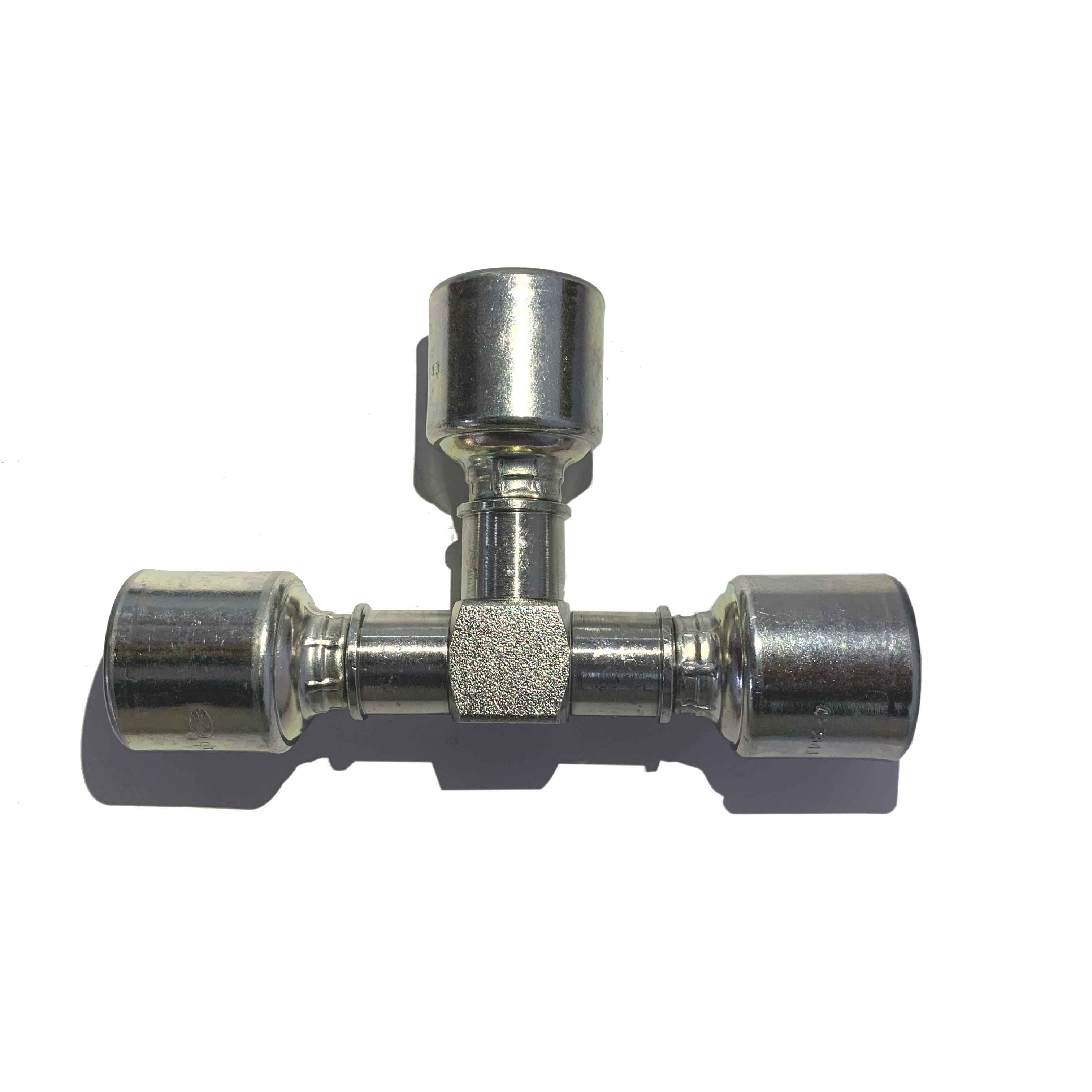
Physical space dictates your routing strategy. You must assess the geometry around valve blocks and manifolds. Sometimes, standard straight connections simply do not fit. You might need 90-degree elbows to maneuver around obstacles. In tight routing scenarios where multiple lines converge, you may require specialized configurations. Specifying a crimp tee joint can neatly split fluid flow without extending the spatial footprint of the manifold. Always measure your clearance before ordering.
Torque management defines the success of your installation. Relying on physical feel invites failure. You must address the dangers of over-torquing and under-torquing. Over-torquing easily cracks cast iron female ports. It distorts metal seats and strips parallel threads. Conversely, under-torquing leaves the connection vulnerable. System vibrations will loosen under-torqued joints rapidly, inviting severe fluid leaks. Always use a calibrated torque wrench and follow manufacturer specifications strictly.
Maintenance teams often attempt to save time by reusing old components. You must avoid this reusability fallacy. Tapered thread fittings seal by actively deforming the metal. Once deformed, they will never seal perfectly again. Similarly, crushed O-rings take a permanent set. They lose their elasticity after initial compression. You should never reuse these items during maintenance cycles. Discard them immediately and install fresh, uncompromised components.
Procurement requires strict vendor evaluation. You cannot afford to purchase unverified components from untraceable sources. Establish clear criteria for your suppliers. Demand full material traceability and documented adherence to SAE/ISO manufacturing standards. Ensure they provide accurate CAD models for your engineering team. Excellent suppliers also offer robust technical support when you require custom hydraulic connection parts for complex machine builds. Prioritize quality assurance over initial purchase price.
Correctly specifying hydraulic threads requires methodical measurement of diameter, pitch, and seat angle.
You must understand the distinct sealing mechanisms of NPT, JIC, ORFS, and BSPP to ensure system-wide integrity.
Dynamic pressure demands and spatial constraints heavily influence your final material and configuration choices.
Strict adherence to installation torque specs prevents costly port cracking and vibration-induced leaks.
Never guess or "eyeball" a connection. The integrity of your fluid system depends entirely on matching the right standard to the right port. A single careless mistake jeopardizes safety and ruins expensive machinery. Consult with a technical specialist or utilize a verified thread identification chart to cross-reference your measurements before placing an order.
A: No. Despite looking similar, they have entirely different thread angles (60° for NPT vs 55° for BSPT) and differing thread pitches. Forcing them together guarantees a severe leak and permanently damages the internal threads of both components.
A: Both are tapered, but NPTF (Dryseal) creates a direct mechanical seal by crushing the thread crests into the roots. This deformation often eliminates the need for Teflon tape or sealant. Standard NPT requires a sealing compound to prevent leaks.
A: Look closely at the sealing requirement. If the port relies on an O-ring, bonded washer, or an angled metal seat to hold fluid, it requires a parallel thread. If the threads themselves act as the seal, it is tapered.
A: No. While they both use straight threads and look virtually identical to the naked eye, JIC uses a 37-degree flare seat. Standard SAE uses a 45-degree flare seat. They will not seal correctly if you mix them.