 English



Views: 0 Author: Site Editor Publish Time: 05-09-2026 Origin: Site


Unmitigated wind-induced dynamics pose a severe engineering challenge for modern power grids. They lead directly to conductor fatigue, strand breakage, and catastrophic grid failures. These invisible mechanical forces degrade critical infrastructure daily. Selecting the right mitigation hardware requires careful balance. You must weigh span length, bundle configuration, and environmental severity against project CAPEX. Engineers face a complex choice in the field. They must select between traditional spacers, dedicated vibration dampers, and hybrid spacer-dampers. Each option presents unique benefits and distinct mechanical limitations.
This article provides an objective framework for comparing these solutions. We will evaluate technical specifications deeply. We also highlight proven methods to mitigate implementation risks. You will learn how to select the most reliable overhead line hardware for utility-scale deployments. By understanding the specific aerodynamic threats, you can optimize your next grid expansion for maximum lifespan.
Distinct Functions: A transmission line spacer primarily maintains bundle geometry and limits sub-span oscillation; a vibration damper dissipates high-frequency aeolian vibrations.
Hybrid Efficiency: Spacer-dampers provide dual-protection for bundled conductors but require more complex, span-specific placement calculations.
Material Standards: Procurement evaluation must prioritize elastomer aging resistance, corona-free designs, and compliance with IEC 61897 or IEEE standards.
OPGW Specifics: Optical Ground Wire (OPGW) hardware requires specialized damper designs to protect fragile internal glass fibers without excessive clamping force.
Grid engineers must first understand the specific aerodynamic forces acting upon overhead cables. High-frequency, low-amplitude vibrations characterize aeolian vibration. These vibrations typically range from 3 to 150 Hz. Steady, laminar crosswinds across open terrain cause this destructive phenomenon. Aeolian vibration remains the primary cause of cumulative fatigue at suspension clamps. The constant upward and downward bending motion stresses the outer aluminum strands mercilessly.
Sub-span oscillation presents a different mechanical challenge entirely. This medium-frequency movement operates between 1 and 3 Hz. It occurs exclusively in bundled conductors due to wake-induced aerodynamics. The windward conductor creates a turbulent aerodynamic wake. The leeward conductor gets caught inside this wake. This turbulent airflow causes violent conductor clashing and severe hardware wear over time. Sub-span oscillation can destroy basic spacers quickly if left unchecked.
Galloping features extremely low-frequency, high-amplitude movement. It usually occurs between 0.1 and 1 Hz. Ice buildup on the conductor typically induces galloping. The ice alters the aerodynamic profile of the cable, creating a makeshift airfoil. Standard dampers and spacers generally cannot prevent galloping. We must establish transparent limitations regarding these extreme ice-induced events. Specialized anti-galloping pendulums handle these specific scenarios.
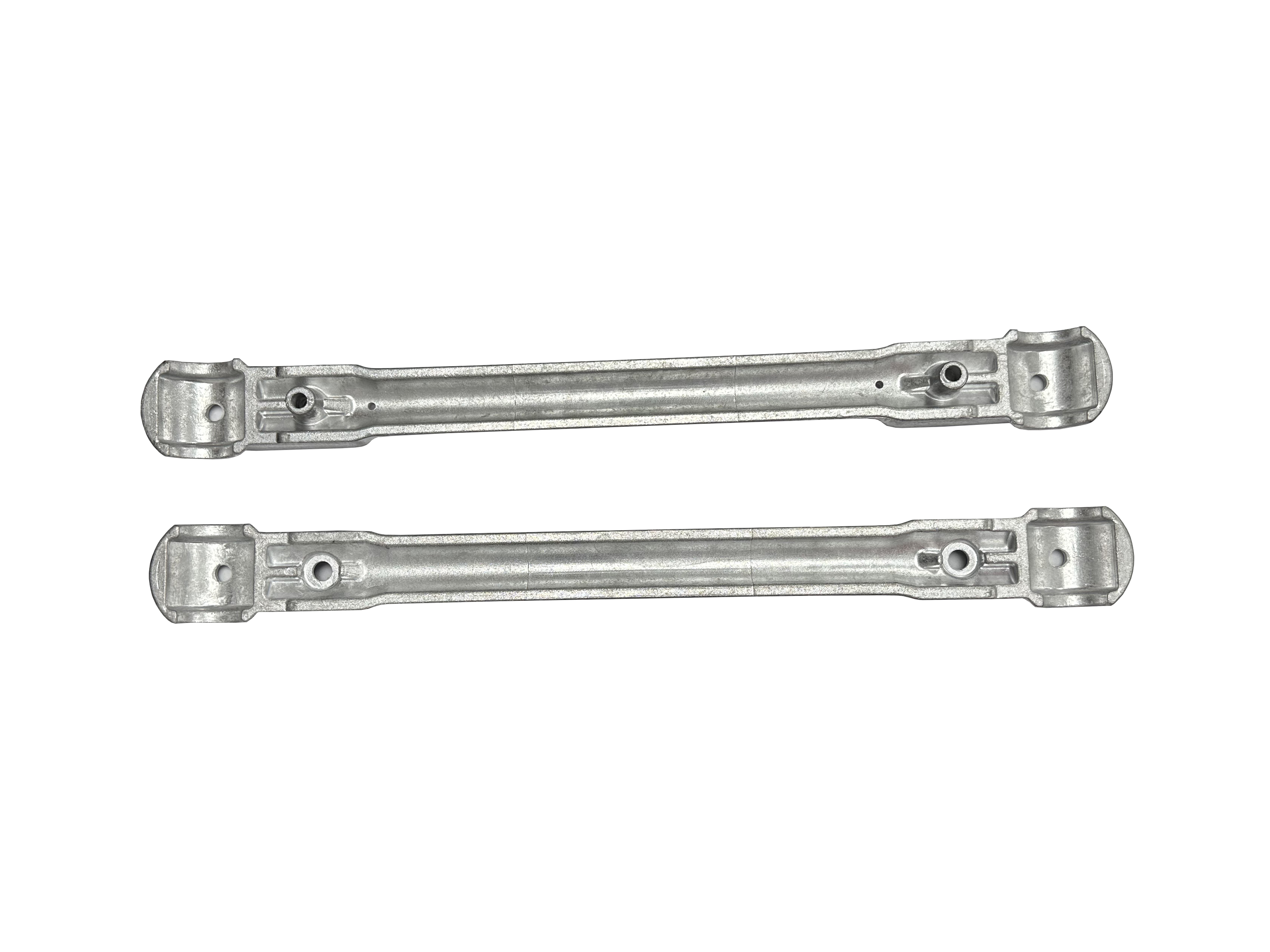
A standard transmission line spacer serves a vital, foundational function in bundled setups. It maintains the exact physical distance between individual sub-conductors. This separation prevents physical clashing and dangerous electrical shorting. Bundled cables increase transmission capacity significantly. However, they rely entirely on spacers to keep their structural integrity intact under heavy wind loads.
Engineers design these components for specific line setups. The configuration taxonomy depends on grid voltage and load requirements. Common designs accommodate Twin, Quad, Hex, and Octagonal bundle configurations. Extra-high-voltage lines often use Hex or Octagonal setups. These complex arrangements require robust spacer frames to maintain the elaborate geometry.
When selecting spacers, you must choose between rigid and flexible models:
Rigid Spacers: These offer highly cost-effective geometry maintenance. They hold the bundle firmly in place. However, they provide zero damping capacity. Rigid frames transfer wind stress directly into the conductor strands. This transfer accelerates localized fatigue.
Flexible/Articulated Spacers: These utilize specialized hinges or semi-conductive elastomer inserts. They allow slight longitudinal movement between the sub-conductors. This minor flexibility offers marginal wear reduction over the hardware's lifespan.
You cannot deploy basic spacers as a standalone solution everywhere. Strict usage constraints apply. They prove totally insufficient in high wind-shear zones. Long-span river crossings also demand more robust damping systems. Relying solely on rigid spacers in high-wind areas guarantees premature strand failure.
A vibration damper neutralizes high-frequency aeolian stress exceptionally well. Stockbridge dampers represent the industry standard. They utilize asymmetric weights attached securely to a specialized messenger cable. When wind hits the main conductor, it begins vibrating. The damper weights oscillate entirely out of phase with the main cable. This opposing physical motion dissipates the destructive kinetic energy. The messenger cable converts this kinetic energy into harmless inter-strand friction and heat.
Dampers remain absolutely essential for unbundled, single conductors. Shield wires placed at the top of transmission towers require heavy damping. High-tension spans crossing valleys also suffer from severe aeolian vibration. You must install dampers near the suspension clamps. This strategic placement intercepts the vibration waves before they strike the rigid clamp body.
Optical Ground Wires demand highly specialized hardware solutions. When evaluating OPGW hardware, standard clamps fail completely. You must evaluate specialized OPGW dampers utilizing preformed armor rods. These structural reinforcing rods distribute clamping stress safely along the cable. They prevent localized crushing of the fragile internal glass fibers. Standard bolted clamps easily destroy optical networks during installation.
Despite their effectiveness against aeolian stress, conventional dampers have distinct limitations. Dampers do not separate sub-conductors. Therefore, they provide zero protection against wake-induced sub-span oscillation across bundled lines. You cannot use them to replace spacers. They serve a dedicated, singular purpose.
Modern engineering merges two critical functions into one unit. Spacer-dampers combine the geometric separation of a traditional spacer with advanced dynamic absorption. They utilize specialized elastomeric hinges to absorb incoming kinetic energy. These rubber elements sit between the clamp arm and the central frame. When the conductors vibrate, the elastomer compresses and stretches. This continuous deformation dissipates the kinetic energy harmlessly.
Performance metrics for these hybrid devices demonstrate superior overall results. They effectively neutralize dangerous sub-span oscillation. Furthermore, they handle mild-to-moderate aeolian vibration efficiently. This dual-protection ensures maximum stability across the entire span. Engineers measure their performance through rigorous laboratory fatigue tests and simulated wind-tunnel environments.
You must evaluate the upfront cost versus the total lifecycle benefit carefully. Spacer-dampers carry a notably higher upfront unit cost than simple rigid models. However, they reduce the immediate need for separate Stockbridge dampers on bundled lines. This hardware consolidation streamlines installation timelines. More importantly, the superior vibration absorption extends overall conductor lifespan significantly. Replacing damaged conductors costs vastly more than premium hardware.
These devices excel in specific environments. Their ideal deployment scenarios involve high-voltage (HV) networks. Extra-high-voltage (EHV) bundled transmission lines in open terrain benefit immensely. Open plains allow wind speeds to increase without obstruction. Spacer-dampers provide the exact dynamic protection these exposed megaprojects require.
Procuring reliable transmission line fittings requires strict adherence to international standards. You cannot rely on visual inspections alone. You must demand empirical testing data.
Elastomer durability forms the foundation of hybrid longevity. Assess the degradation curve of the rubber components aggressively. They face severe daily UV exposure and extreme temperature fluctuations. Furthermore, corona discharge generates ozone. Ozone attacks natural rubber mercilessly. High-grade EPDM or semi-conductive silicone must be utilized to survive these harsh atmospheric conditions.
Clamp design and slip load dictate mechanical safety. The clamping mechanism must hold the conductor firmly under massive wind loads. However, it should never damage the outer aluminum strands during routine thermal expansion. A poorly designed clamp will scar the cable. These micro-scars become starting points for devastating fatigue fractures.
Corona and Radio Interference Voltage (RIV) require careful evaluation. Hardware profiles must offer smooth, corona-free performance. Sharp edges on clamps create massive electrical stress gradients. These gradients cause localized corona discharges on lines exceeding 220kV. Corona discharge wastes energy and accelerates elastomer degradation.
Compliance and testing separate premium vendors from budget suppliers. Shortlist vendors providing documented fatigue testing and wind tunnel simulations. Ensure strict compliance with IEC 61897 for dampers. Verify IEC 61854 compliance for spacers. These international benchmarks guarantee minimum performance baselines.
Hardware Type | Primary Function | Aeolian Damping | Sub-Span Damping | Ideal Deployment |
|---|---|---|---|---|
Rigid Spacer | Geometry maintenance | None | Low | Sheltered, short spans |
Vibration Damper | Vibration dissipation | High | None | Single conductors, OPGW |
Spacer-Damper | Separation + Damping | Moderate | High | EHV bundled lines, open terrain |
Selecting superior hardware solves only half the engineering equation. Improper field execution will negate the best component designs instantly. You must calculate placement meticulously.
The math of placement prevents failure. Arbitrary placement guarantees disaster. You must calculate precise nodal points accurately. Nodal points represent areas of zero movement on a vibrating string. Placing a damper on a true node renders it completely useless. Engineers base these calculations on span length, conductor tension (EDS), mass-per-unit length, and prevailing wind frequencies. Specialized software usually handles these complex algorithms.
Staggered spacing remains crucial for bundled lines. Installing spacers at perfectly equal distances risks creating massive resonant frequencies. The wave energy simply passes through the entire span unchecked. You must implement asymmetrical sub-span intervals. This deliberate spacing disruption breaks wave synchronization effectively. It prevents the sub-spans from oscillating in unison.
Installation errors compromise the entire system immediately. Torque failures plague field installations globally. Under-tightening allows dangerous clamp slippage. Over-tightening crushes the aluminum strands instantly. To eliminate this risk, adopt the following best practices:
Require shear-head bolts on all critical clamps. These bolts snap off exactly when the proper torque is reached.
Mandate calibrated torque wrench protocols for all line crews.
Utilize preformed armor rods on fragile lines to distribute radial pressure evenly.
Conduct immediate post-installation visual checks on all bolt heads.
Routine inspection baselines ensure long-term grid security. Do not install hardware and forget it. Set aggressive drone inspection schedules. Implement thermal imaging to detect hot spots near suspension clamps. Monitor elastomer degradation and check for clamp slippage continuously. Early detection prevents catastrophic line drops.
Selecting the proper overhead hardware demands a clear understanding of dynamic forces. We can summarize the fundamental decision matrix simply. Use dedicated dampers for single unbundled lines and critical OPGW networks. Deploy rigid spacers only in highly sheltered or exceptionally short spans. Choose elastomeric spacer-dampers for all high-voltage and extra-high-voltage bundled networks.
Prioritize reputable power line fittings vendors valuing strict engineering standards. Demand proprietary placement software from your suppliers. Insist on transparent wind-tunnel testing data and comprehensive metallurgical reports. Do not base critical grid infrastructure decisions strictly on lowest-bidder pricing. Premium components prevent catastrophic failures, saving millions in emergency repair costs over the network's lifespan.
A: No. Standard spacers only prevent clashing. Only spacer-dampers with elastomeric damping elements can perform both functions.
A: Quantity is determined by dividing the total span length by the maximum allowable sub-span length (typically 50-70 meters), adjusted asymmetrically to prevent harmonic resonance.
A: While metal fittings can last 40+ years, the elastomeric damping components in spacer-dampers typically dictate a functional lifespan of 20-30 years, depending on UV and ozone exposure.
A: OPGW contains fragile optical fibers. Standard damper clamps can crush the core; OPGW-specific dampers use structural reinforcing rods (armor rods) to distribute the radial clamping pressure.