 English

Views: 0 Author: Site Editor Publish Time: 11-06-2026 Origin: Site


Positional accuracy is a critical factor in valve body machining. Even the smallest misalignment can cause significant performance issues.
In this article, we will explore common challenges faced during valve body machining and how to overcome them. You'll learn practical solutions to improve machining precision, reduce errors, and ensure quality valve production.
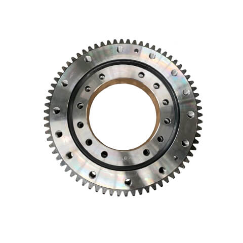
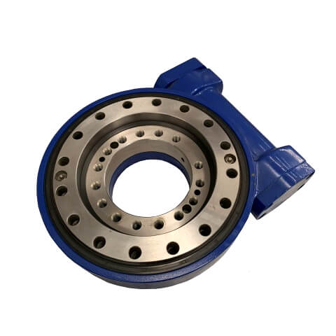
Valve body machining is a precision manufacturing process that involves shaping and refining the core components of a valve, typically using materials like cast iron, cast steel, or stainless steel. The goal is to produce a component with exact dimensions, allowing it to control the flow of fluids or gases accurately.
In the machining of valve bodies, key operations include turning, boring, and milling. These processes require high precision to meet stringent industry standards. Given the intricate design of valve bodies, maintaining positional accuracy throughout the machining process is essential.
Tip: Using high-quality raw materials like stainless steel or brass can significantly reduce machining time while improving end-product durability.

Positional accuracy refers to the precision with which the machined features of a valve body, such as bore holes and external diameters, are positioned relative to other features. High positional accuracy ensures that each part fits perfectly into the final assembly and performs as intended.
Valve bodies with poor positional accuracy can cause issues like leakage, inefficient flow control, and increased wear and tear. As a result, achieving tight tolerances (e.g., ±0.05 mm) is critical for manufacturers to produce functional and reliable valve systems.
Factor | Description | Impact on Accuracy |
Mechanical Components | Rigidity of machine structure, ball screws, spindle | Directly affects the precision of tool positioning |
Control System | Accuracy of feedback systems, encoders, motors | Influences precision of tool movement and cutting |
Thermal Effects | Thermal expansion due to cutting forces and machine heat | Affects dimensional stability and accuracy |
Environmental Conditions | Vibration, humidity, cleanliness | Can degrade positioning accuracy over time |
One of the most common causes of positional accuracy issues in valve body machining is the use of V-block fixtures during the machining process. While V-blocks are designed to stabilize the workpiece, they can introduce errors if not properly aligned.
V-block positioning errors occur due to slight shifts in the fixture during machining. These errors can accumulate and result in misalignment between critical features, leading to products that do not meet the required tolerance. As shown in several studies, V-block positioning errors can significantly impact the machining of holes and other key features, exceeding positional tolerance limits.
Consider using flat positioning surfaces instead of V-blocks to minimize datum shift errors and improve overall accuracy.
Datum shift refers to the misalignment of the reference points used for machining, which can cause dimensional inaccuracies. In the case of valve body machining, the outer diameter centers are typically used as reference points or "datums" for the machining process.
When the workpiece shifts during machining, it leads to misalignment between features. This shift may cause critical features like bore holes and external diameters to be positioned incorrectly, impacting the final product's functionality.
Revising the machining process route is one of the most effective solutions for improving positional accuracy. By recalibrating the datum during the finishing stage, manufacturers can ensure that any V-block induced errors are corrected.
A key change is to introduce a "finish boring" step before the drilling process. This adjustment ensures that the final reference point for machining aligns with the finished features, minimizing errors and improving the overall machining outcome.
Measurement Technique | Accuracy Range | Equipment Required | Key Applications |
Laser Interferometry | 0.01 µm to 1 µm | Laser interferometer | High-precision measurement |
Ball Bar Testing | 0.01 mm to 0.1 mm | Ball bar | Identifying geometric errors |
Heidenhain System | 0.1 µm to 1 µm | Linear scale system | Real-time feedback on positioning accuracy |
Straightness Testing | 0.01 mm to 0.1 mm | Dial indicators, levels | Detect misalignment and geometric errors |
The design of machining fixtures plays a pivotal role in achieving accurate valve body machining. While V-blocks are commonly used, they are not always the best option for precise machining. Instead, flat positioning surfaces are increasingly being used to reduce errors caused by V-blocks.
By replacing V-blocks with more stable positioning systems, manufacturers can reduce errors related to datum shift. Additionally, these alternative fixtures can enhance repeatability, ensuring consistent results across multiple machining cycles.
Always assess fixture design for potential accuracy issues before starting production to avoid costly errors later on.
Achieving tighter machining tolerances, such as reducing the outer diameter tolerances of critical features (e.g., φ205h8 to φ205h6), can improve positional accuracy. However, this requires a balance between cost and precision.
While tighter tolerances may enhance accuracy, they can also increase machining time, raise operational costs, and demand higher-precision machinery. For mass production, manufacturers need to evaluate whether the investment in achieving tighter tolerances justifies the improvement in accuracy.
CNC (Computer Numerical Control) machines have revolutionized the machining industry by offering high precision, repeatability, and flexibility. Modern CNC systems, equipped with high-precision feedback mechanisms like encoders and resolvers, can dramatically improve the positioning accuracy of valve bodies.
By integrating these advanced CNC systems into the machining process, manufacturers can ensure that the tool paths are followed with minimal deviations, enhancing the overall precision of each part. Additionally, CNC systems can adjust in real time based on feedback, compensating for small inaccuracies during machining.
Automation plays a key role in improving the accuracy and efficiency of valve body machining. CNC systems, which operate with little to no human intervention, reduce the risk of errors caused by operator fatigue, inconsistencies, and manual mistakes.
Automated systems also enable manufacturers to optimize cutting parameters, adjust machine movements based on real-time data, and ensure that each valve body is machined with the same precision. This helps improve positional accuracy across large production runs.
The original machining process for valve bodies relied heavily on V-block fixtures and the use of outer diameter centers as reference points. While this process was efficient, it led to issues with positional accuracy, particularly with the positioning of holes on the outer diameter end faces.
To address the accuracy issues, several key changes were made to the process:
● The introduction of finish boring before drilling to recalibrate the datum.
● The replacement of V-blocks with more stable flat positioning surfaces.
● Modifying fixture designs to ensure better alignment during machining.
The revised process significantly improved positional accuracy, reducing errors related to V-block positioning. Key benefits included enhanced product quality, fewer rejects, and increased operational efficiency.
To ensure that valve body machining remains precise over time, regular machine calibration and maintenance are essential. This includes checking the alignment of CNC systems, updating feedback systems, and ensuring that all moving parts are functioning correctly.
Tip: Schedule regular maintenance and calibration to prevent small inaccuracies from developing into larger issues over time.
Implementing stringent quality control measures and monitoring systems throughout the machining process can help identify positional inaccuracies early. By investing in real-time monitoring systems, manufacturers can detect issues before they affect product quality, allowing for immediate adjustments to the process.
This article discusses how to address positional accuracy issues in valve body machining. By analyzing the root causes of errors and proposing effective process improvements, manufacturers can significantly enhance machining precision. JOC Machinery Co., Ltd. offers advanced machining solutions that ensure high-quality, accurate valve body production, providing reliable performance for various industrial applications.
A: Valve body machining refers to the process of shaping and refining valve bodies used in various systems. It ensures precise fit and functionality for controlling fluid flow.
A: Positional accuracy ensures that all components align properly, preventing leaks or malfunctions in the valve body. This precision is crucial for system efficiency and safety.
A: Improving accuracy involves refining machining processes, such as recalibrating the datum during finishing steps and optimizing fixture designs to prevent errors.
A: Common challenges include alignment errors, inconsistent machining tolerances, and fixture-related inaccuracies that affect the final product’s precision.
A: JOC Machinery Co., Ltd. utilizes advanced CNC machining technologies to ensure high-precision valve body production, meeting stringent accuracy standards.