 English



Views: 0 Author: Site Editor Publish Time: 31-08-2026 Origin: Site


Specify a tolerance too loose, and your shaft fails in assembly. Specify it too tight, and you trigger exponential cost increases and delayed lead times. In the procurement and engineering of CNC Machining Parts, shaft tolerancing remains a primary driver of unit economics. Over-tolerancing non-critical dimensions stands out as the most common DFM (Design for Manufacturing) error engineers make today. Too often, drawings demand ultra-tight specifications on every single surface simply because the CAD software defaulted to a specific decimal place. This oversight drives up manufacturing complexity unnecessarily and causes severe quoting bottlenecks.
This comprehensive guide breaks down how to align tolerance specifications with actual functional requirements. We will help you balance high-end precision against realistic manufacturability. You will discover the financial impacts of strict margins and learn to evaluate dimensional limits by application. We will also explore the critical role of geometric controls, fit systems, and material behaviors. Let us look at the essential rules to optimize your engineering drawings right now.
Standardizing to ISO 2768 (medium or fine) for non-mating surfaces prevents unnecessary machining costs.
Tight shaft dimensional tolerance should be strictly reserved for bearing fits, seal interfaces, and gear mounts.
Geometric Dimensioning and Tolerancing (GD&T)—specifically runout and concentricity—is often more critical for dynamic shafts than basic diametric tolerance.
Material selection (e.g., specifying a custom steel shaft vs. aluminum) dictates thermal stability and affects the machinist’s ability to hold micro-inch tolerances.
Moving from a standard ±0.005” (±0.127mm) to ±0.0005” (±0.0127mm) does not merely double the manufacturing cost. It can quadruple it. You are not just paying for a slightly sharper cutting tool. You are buying slower feed rates, frequent insert changes, and highly controlled machining environments.
When you shrink the acceptable margin of error, you force process step-ups. Standard CNC turning centers easily handle ±0.005” in a single efficient operation. Drop that requirement to ±0.0005”, and manufacturers must immediately transition to secondary operations. They will use specialized cylindrical grinding, honing, or lapping machines to hit those micro-inch windows. These extra setups consume massive amounts of labor hours and require specialized machine operators.
Furthermore, tight limits drastically elevate scrap rates. If a machinist targets a microscopic window, a tiny tool deflection ruins the entire part instantly. Inspection protocols also become highly intensive. Quality control teams cannot use standard calipers to verify these dimensions reliably. They must deploy Coordinate Measuring Machines (CMMs) or precise optical comparators. The buyer absorbs all these specialized metrology expenses directly. You effectively pay for the time spent measuring the part, not just cutting it.
Common Mistake: Applying blanket title-block tolerances to the entire drawing drives up costs uniformly, even on empty clearance zones.
Best Practice: Keep tight specifications strictly localized to functional interfaces.
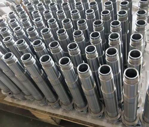
You must evaluate shaft dimensional tolerance based directly on the actual physical mating conditions it faces in assembly. Treating all diameters equally guarantees budget overruns.
Clearance Fits (Loose to Running): These describe shafts moving freely inside a bore. Common designations include RC1 through RC9. Use these primarily for pivot pins, hinges, or low-speed rotational shafts. They forgive slight misalignments and keep fabrication highly economical. You rarely need complex grinding for an RC clearance fit.
Transition Fits: These balance exact location requirements against assembly ease. Ranging from LC1 to LC11, transition fits ensure precise alignment without requiring heavy hydraulic pressing force. You will commonly apply them to alignment pins or mechanisms needing occasional manual disassembly. They require careful turning but generally avoid secondary grinding.
Interference (Press) Fits: High-stakes applications demand these extreme limits. Examples include FN1 to FN5. You need press fits to permanently secure bearings, gears, and drive pulleys. Engineering teams usually follow the ANSI/ISO hole-basis limits and fits system here. In the hole-basis system, you keep the bore to a standard reamer size because reamers cut fixed diameters. Then, you adjust the shaft's diameter to create the precise interference.
You should match the application to the exact standard tolerance band using a simple framework. A high-speed precision mainshaft demands very different numbers than a stationary structural mount.
Table 1: Shaft Application Decision Matrix
Application Scenario | Common ISO Tolerance Band | Expected Fit Behavior | Machining Complexity |
|---|---|---|---|
Stationary Pivot / Structural Mount | h9, h11 | Clearance (Loose to Free) | Low (Standard CNC Turning) |
Standard Alignment Pin | h7, j6 | Transition (Snug to Locational) | Medium (Precise Turning) |
High-Speed Precision Mainshaft | h6, g6, m6 | Interference (Press to Shrink) | High (Turning + Cylindrical Grinding) |
Why is basic diameter control not enough? A shaft can measure perfectly within diametric limits but still look visibly bowed. Engineers colloquially call this the "banana effect." If you only control size, you completely ignore form. Geometric Dimensioning and Tolerancing (GD&T) solves this functional gap.
Total Runout vs. Circular Runout: You must control dynamic balance strictly for high-RPM applications. Catastrophic vibration destroys bearings rapidly if left unchecked. Circular runout controls a single cross-section of the rotating shaft. Total runout controls the entire cylindrical surface simultaneously along the datum axis. Specify total runout when the whole shaft surface interacts dynamically with a mating component.
Concentricity and Cylindricity: Use these strict geometric controls very carefully. Concentricity ensures the central axis of a cylinder perfectly matches a datum axis. Cylindricity forces the entire 3D surface into a perfect tube shape. While mathematically pure, these callouts are notoriously difficult to inspect. Often, standard positional tolerances or simple runout achieve the exact same functional goal at a fraction of the inspection price.
Implementation Risk: Avoid over-applying GD&T. Many engineers put concentricity callouts on single-setup lathe parts. The CNC machine's inherent rigidity already guarantees standard concentricity naturally during a single continuous cut. By adding the callout, you add extensive CMM inspection costs without actually changing the cutting process at all.
Material selection directly impacts what dimensions your machinist can actually hold repeatedly. You cannot divorce your dimensional requirements from your metallurgical choices.
Machinability and Deflection: The rigidity of carbon steel supports tighter bounds beautifully. Think of sturdy alloys like 1045 or 4140. A custom steel shaft resists cutting tool pressure exceptionally well. Conversely, softer materials like 6061 aluminum or Delrin plastics deflect away from the cutting insert. This natural deflection makes holding a ±0.0005” margin maddeningly inconsistent across a production run.
Thermal Expansion Variables: Aggressive machining generates intense, localized heat. A component might measure perfectly while hot in the lathe chuck. However, once it cools to room temperature in the inspection lab, it shrinks out of spec. You must account for thermal growth. A tolerance held perfectly at room temperature shifts dramatically if the part overheats during rapid turning operations.
Residual Stress and Warpage: Cold-rolled steel often hides immense internal residual stresses. When the cutting tool removes material, it releases those trapped stresses unevenly. The steel naturally bows or twists. For highly precise parts, stress-relieving or annealing steps become a necessary prerequisite before final finishing. This extra thermal step stabilizes the metal lattice and prevents frustrating post-machining warpage.
Follow these practical steps to lock in your engineering drawings accurately. This systematic approach ensures you only pay for precision where you actually need it.
Step 1: Default to Standard (ISO 2768-m): Start your drawing here. Apply this medium standard to all non-mating lengths, cosmetic chamfers, and thread reliefs. Do not overthink the empty spaces. Let standard machining practices handle the bulk of the geometry.
Step 2: Isolate Critical Interfaces: Apply the restrictive limits (like +/- 0.0005” or h6) strictly to bearing journals, seal glands, and drive interfaces. Limit the expensive manufacturing zones to fractions of an inch rather than the entire shaft length.
Step 3: Review Aspect Ratios: Look carefully at your length-to-diameter (L:D) ratio. Shafts exceeding a 10:1 ratio start whipping during rotation. They require steady rests or tailstocks to support the cut. This added setup complicates the machinist's ability to adhere to strict numbers without inducing chatter.
Step 4: Supplier Alignment: Talk to your fabrication partner early. Communicate the actual functional intent. Tell them, "This journal mates with a 6204 bearing," instead of just dropping a generic tight block on the drawing. This context helps the machine shop pick the absolute best manufacturing strategy.
Specifying the right CNC machined shaft tolerances is ultimately an exercise in functional restraint. You must resist the urge to over-engineer empty spaces. Here are your final actionable takeaways:
Align your numbers with standard ANSI/ISO fit tables to eliminate guesswork.
Reserve tight specifications exclusively for critical mating surfaces to protect project budgets.
Account for material properties like thermal expansion and tool deflection before finalizing decimal places.
Remember that total runout often controls dynamic balance better than simple diameter constraints.
As a next step, we strongly urge buyers to audit their current CAD drawings. Look for outdated blanket tolerances causing unnecessary quoting friction. Consult your manufacturing partner’s DFM engineering team before you request a final quote. Open communication prevents costly over-engineering and ensures reliable, long-lasting assembly performance.
A: The baseline standard for non-critical features is ISO 2768 medium (m) or fine (f). For typical nominal sizes, this usually translates to around ±0.1mm. This standard covers all cosmetic lengths, chamfers, and clearances, keeping basic machining fast and highly cost-effective.
A: Long shafts inherently have high length-to-diameter (L:D) ratios. They suffer from tool chatter and heavy material deflection during cutting. Holding tight numbers requires specialized setups like steady rests or tailstocks. These manual interventions drastically slow down cycle times, increasing the final part price.
A: You should generally follow the "hole-basis" system. Standard engineering preference dictates keeping the bore standard because reamers and broaches cut fixed sizes. You then apply the specific tolerance adjustments to the shaft diameter to create the desired clearance or interference fit.
A: Stable materials like 4140 alloy steel, 303 stainless steel, or pre-ground stock work best. Material stability dictates your final tolerance capabilities. These rigid metals resist tool deflection and maintain excellent thermal stability, allowing machinists to hold micro-inch numbers consistently.