 English



Views: 0 Author: Site Editor Publish Time: 20-08-2026 Origin: Site


Slewing bearings form the absolute critical core of heavy machinery. A single structural failure results in catastrophic equipment downtime. Worse, it creates severe safety hazards on active job sites. Specifying these massive components requires precise engineering focus. It is never a simple, one-size-fits-all process. The operational demands of a stationary tower crane vastly differ from those of a continuously moving track excavator. Equipment designers need a reliable method to choose the best rotational parts. This article introduces a definitive, engineering-first framework. You will learn how to properly evaluate and shortlist the right components. We base this methodology on verified load data, structural integrity, and application-specific realities. Let us dive into the exact criteria required to keep your machinery turning safely and efficiently under extreme loads. This proactive approach prevents disastrous structural failures.
Equipment dictates the load profile: Cranes demand high resistance to tilting moments, while excavator bearing load profiles must account for severe dynamic shocks.
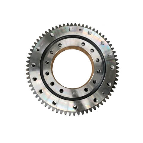
Gearing matters: Selecting an external gear slewing bearing versus an internal configuration fundamentally alters maintenance access and pinion integration.
Look beyond standard charts: Accurate slewing bearing selection requires factoring in structural rigidity, mounting surface flatness, and application-specific safety factors.
Vendor verification is critical: Shortlist suppliers based on verifiable material certifications, destructive testing data, and custom engineering support, not just baseline pricing.
Heavy machinery operates in highly unforgiving environments. We must thoroughly analyze the specific operational profile before making any structural component choices. A component designed for smooth rotation will shatter under heavy shock impacts.
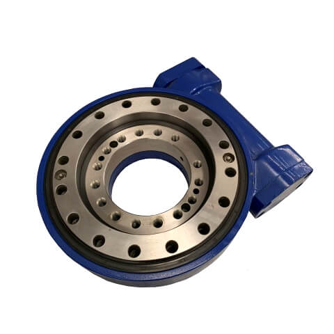
Cranes primarily perform static, heavy-lifting tasks. They suspend massive payloads high in the air at extreme radiuses. This specific geometry creates tremendous overturning moments at the machine's base. A high-quality crane slewing ring must withstand these intense gravitational forces. It also needs to resist severe wind loads during prolonged stationary periods. Engineers apply strict safety factors to these designs.
You will often see safety factor requirements ranging from 1.33 to 1.5 or higher. Regional compliance standards heavily dictate these exact multipliers. Overturning moments try to pry the upper structure away from the undercarriage. Therefore, the raceway geometry must lock the rolling elements securely in place. The design prioritizes extreme axial load capacity combined with exceptional moment resistance.
Earthmoving equipment faces a completely different mechanical reality. Excavators undergo continuous, repetitive rotational stress during every single shift. They generate severe vibration throughout the entire digging cycle. An accurate excavator bearing load profile demands high radial capacity above all else. It must demonstrate incredible resilience against sudden, jarring impacts.
Consider a scenario where an excavator bucket suddenly strikes solid granite hidden underground. This massive kinetic shock travels directly up the boom and into the rotational joint. Excavators also require highly specialized sealing solutions. Abrasive dust, wet mud, and acidic water constantly threaten the internal raceways. Standard industrial seals fail quickly in these trenches. You must specify robust barrier seals to prevent contamination ingress and rapid wear.
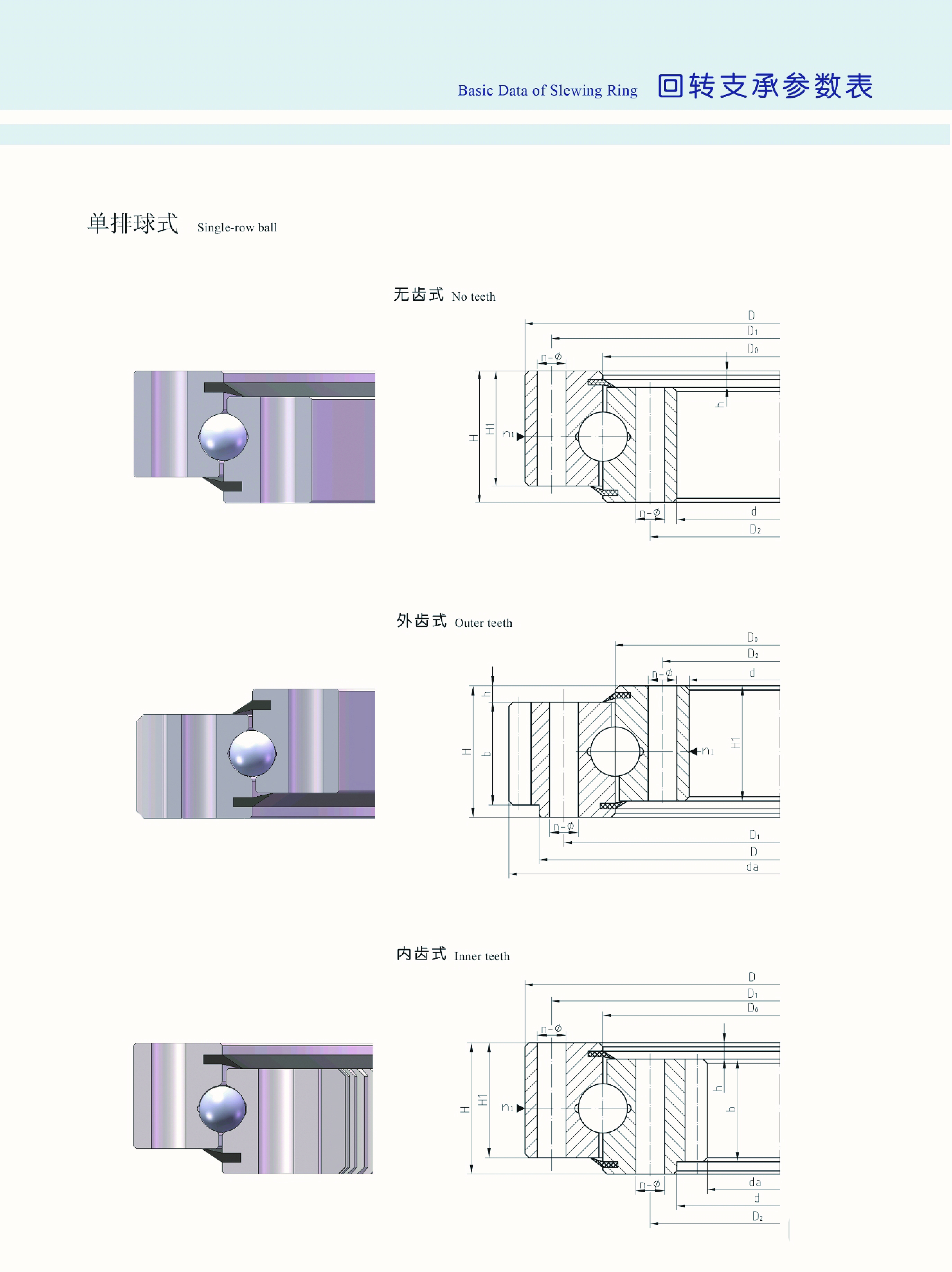
Next, we must examine how rotational torque transfers between the drive motor and the superstructure. The mechanical relationship connecting the Bearing & Gear represents a primary decision point in equipment design. Getting this wrong leads to premature pinion failure and excessive maintenance costs.
Rotational torque moves from a hydraulic or electric drive motor through a pinion gear. This pinion meshes directly with teeth cut into one of the slewing rings. You must decide whether these teeth belong on the inner ring or the outer ring. This choice impacts the entire chassis layout.
Equipment designers usually choose between two main drive setups. Each configuration offers distinct mechanical and operational advantages.
External gear configurations: An external gear slewing bearing maximizes the pitch diameter of the gear mesh. This larger diameter requires less torque from the drive motor to turn the machine. It provides simplified visual inspection routines. Maintenance crews can easily observe tooth wear and apply manual lubrication. We highly recommend this option for machines constrained by tight internal housing space.
Internal gear configurations: Sometimes the primary drive motor requires extra physical protection. An internal gear setup keeps the motor and pinion entirely inside the equipment chassis. The heavy steel outer frame shields the delicate mesh from severe environmental hazards. It prevents catastrophic damage from falling rocks, debris, or deep mud.
Certain applications require entirely independent drive systems. You do not always need gear teeth machined into the bearing ring. Gearless setups work exceptionally well for specialized lifting platforms. These platforms often utilize secondary friction drives or external belt systems to control rotation. Removing the gear teeth simplifies manufacturing and reduces the initial component weight.
Proper slewing bearing selection relies entirely on choosing the right internal rolling elements. We must match the internal structural framework to the expected operational load limits. You cannot swap configurations without completely recalculating the safety margins.
Ball bearing designs provide highly cost-effective rotational solutions. They offer excellent low-friction movement. However, they carry strict physical load limitations. You will find single-row setups appropriate for light-duty cranes and smaller mini-excavators. Double-row designs add significant stability by distributing forces across two raceways. Yet, they still fall short when facing massive, industrial-scale overturning moments.
Cross-roller configurations offer superior structural stiffness compared to ball designs. The cylindrical rollers alternate their orientation at 90-degree angles. This geometry delivers exceptional rotational accuracy. These components handle simultaneous radial, axial, and moment loads highly effectively. You should specify cross-roller configurations when load stability and precise positioning matter most.
Massive earthmoving and lifting equipment requires extreme heavy-duty solutions. Three-row roller bearings separate the axial and radial load paths entirely. The design uses horizontally oriented rollers for axial loads and vertically oriented rollers for radial loads. This distinct engineering advantage prevents complex stress concentrations inside the raceway. We position this configuration as the optimal choice for maximum-capacity offshore cranes. Ultra-large mining excavators also rely heavily on this robust architecture to survive decades of abuse.
Never guess your theoretical limits. Always cross-reference your calculated dynamic loads against the manufacturer's specific static limit curve. You must run thorough rating life calculations to guarantee safety over time. Engineers utilize finite element analysis to visualize how loads transfer through the rolling elements.
Table 1: Comparison of Common Slewing Bearing Structures
Internal Structure Type | Primary Load Strength | Stiffness Level | Ideal Machinery Application |
|---|---|---|---|
Single-Row Ball | Light Axial & Radial | Low to Moderate | Mini-excavators, light utility cranes |
Double-Row Ball | Moderate Moment | Moderate | Mid-sized mobile cranes |
Cross-Roller | Simultaneous Multi-directional | High | Precision positioning cranes, compact equipment |
Three-Row Roller | Extreme Axial & Moment | Very High | Offshore cranes, massive mining excavators |
Even the highest quality components fail rapidly under poor implementation. Theoretical limits mean nothing if the physical installation introduces fatal flaws. Let us look at common installation pitfalls and how you can proactively avoid them.
A slewing ring is only as rigid as the steel structure mounted underneath it. You must bolt the component to a perfectly flat, precisely machined surface. Mounting surface irregularities cause severe operational problems. Out-of-flatness creates localized hard spots along the raceway. As the equipment rotates, rolling elements pinch at these tight spots. These hard spots lead directly to rapid raceway degradation and early catastrophic failure.
Bolts hold the entire rotational assembly together. You must specify high-tensile, precisely pre-tensioned bolts for every installation. Improper tensioning procedures introduce massive structural risks. Uneven clamping forces lead directly to premature bolt fatigue. One loose bolt transfers extreme stress to its neighbors. Over time, this cascading fatigue causes complete, catastrophic separation between the superstructure and the undercarriage.
Always clean the bolt threads and mounting holes thoroughly before installation.
Use a calibrated hydraulic torque wrench to achieve exact clamping force.
Follow a strict star-pattern tightening sequence to ensure even load distribution.
Re-torque all fasteners after the first 100 hours of equipment operation.
High-friction environments destroy standard lubricating grease very quickly. You must critically evaluate the realities of grease breakdown in the field. High heat and extreme pressure alter the lubricant's fundamental chemical properties. Once the oil separates from the thickener, metal-on-metal contact begins.
Furthermore, standard nitrile seals struggle immensely in highly abrasive environments. They tear easily on jagged debris. You should upgrade to advanced labyrinth sealing systems for severe mining and earthmoving applications. These complex seals create a physical maze. They block contaminants from ever reaching the vital rolling elements.
Procurement goes far beyond simply checking catalog dimensions. You need verifiable proof of engineering quality from your potential suppliers. The cheapest upfront option often becomes the most expensive mistake.
Instruct your buying teams to ask for highly specific engineering data. Request detailed static and dynamic load capability charts tailored to your machine. Ask for comprehensive gear tooth strength calculations based on your exact pinion torque. Demand CAD and 3D models. You need these files to run your own independent finite element analysis on the chassis integration.
Base metallurgy dictates long-term component survival. Require undeniable proof of raceway induction hardening depths. If the hardened layer is too shallow, the raceway will crush under load. Ensure the core material possesses high impact toughness to survive shock loads. Common industry specifications include 42CrMo or 50Mn forged steel. Ask for destructive testing data and mill certificates to confirm these physical properties before signing any purchase orders.
Frame your critical purchasing decision around long-term lifecycle longevity. Do not fixate solely on the upfront unit price tag. Low-quality components often fail thousands of hours early. You must factor in the massive cost of replacement downtime. A failed ring grounds an entire construction site. Consider the maintenance intervals and replacement labor during your final vendor evaluation. An expertly engineered, highly durable part saves immense capital over ten years of continuous, grueling operation.
Choosing the right rotational assembly bridges a critical engineering gap. It connects theoretical mechanical limits to the harsh realities of active construction sites. Decision-makers must consistently prioritize empirical load data and robust structural compatibility over generic catalog specifications. Cranes need incredible resistance to overturning moments. Excavators demand unmatched resilience against constant, violent shock loads.
Matching the internal rolling elements and gear configurations to your specific machine ensures safe, reliable performance. A properly specified and meticulously installed ring will deliver thousands of trouble-free operating hours. We highly recommend seeking expert guidance before finalizing any equipment designs. Contact our engineering support team for a custom load profile assessment, or download our technical sizing guide to begin your next project today.
A: You calculate the equivalent load using a specialized formula combining the maximum axial load, radial load, and total tilting moment. Engineers apply an application-specific safety factor based on the equipment type. You plot this final equivalent load against the manufacturer's static limit curve to verify structural safety.
A: Engineers measure lifespan in theoretical rotational hours, known as L10 life. A high-quality assembly typically ranges from 10,000 to 30,000 operating hours. However, this lifespan depends heavily on strictly following consistent lubrication schedules, maintaining proper bolt tension, and never exceeding designated capacity limits.
A: We highly recommend roller configurations when your machinery operates under extreme tilting moments or faces violent shock impacts. Cylindrical rollers provide a vastly larger contact area against the raceway than spherical balls. This geometry delivers maximum structural rigidity and prevents the steel from yielding under immense pressure.
A: As a pragmatic baseline, manually lubricate the raceways and gear teeth every 50 to 100 operating hours for active equipment. However, severe conditions involving heavy mud, corrosive saltwater, or constant rotation require continuous auto-lubrication systems to prevent rapid grease degradation and metal-on-metal wear.