 English



Views: 0 Author: Site Editor Publish Time: 22-08-2026 Origin: Site


Custom gear specification carries extremely high stakes for industrial equipment design. Standard off-the-shelf components frequently fail under strict spatial limitations. They also struggle to manage extreme torque and harsh environmental conditions. Poorly specified components lead to premature system failure and operational downtime.
Mechanical engineers constantly face a tough dilemma. You must balance optimal mechanical efficiency against the need for massive speed reduction. Finding spatial economy further complicates your drivetrain layout decisions. Helical setups provide smooth speed transitions, while worm setups conquer tight spacing challenges.
This guide provides a clear, engineer-focused framework. You will discover how to evaluate and specify crucial drivetrain elements. We cover everything from profile geometry to systemic load management. Following these principles helps you source reliable custom assemblies. You can confidently prevent catastrophic breakdowns and control long-term operational expenses.
Efficiency vs. Reduction: Custom helical gears deliver 90-98% efficiency for high-speed continuous use; worm gears excel in high-reduction, right-angle applications with limited space.
Load Management is Systemic: Specifying a gear without accounting for the accompanying bearing setup will lead to rapid wear due to unmanaged axial and radial loads.
Material Selection is Critical: Precise gear material specification dictates thermal management and wear resistance, especially in high-friction worm setups.
Vendor Vetting Requires Data: Shortlist manufacturers based on their ability to provide AGMA-compliant QA documentation, exact tolerance matching, and application-specific prototyping.
Identifying when standard catalog gears introduce unacceptable performance compromises remains a critical business challenge. Catalog gears assume ideal mounting conditions and standardized load profiles. Real-world industrial machinery rarely offers these perfect conditions. When standard options fail your spatial or torque requirements, custom engineering becomes necessary.
You should specify a custom helical gear when your application demands continuous high-speed operation. These gears offer incredibly low acoustic signatures. They also provide maximum power transmission efficiency. Their angled teeth engage gradually. This smooth engagement reduces shock loading and vibration during heavy use. You get high mechanical throughput and long service life.
Conversely, you should specify a worm gear when requiring massive speed reduction in a single stage. They deliver highly compact right-angle power transmission. You might also need specific self-locking capabilities. This anti-back-drive function prevents heavy loads from reversing under gravity. They solve space constraint problems beautifully.
Sometimes neither option fits your specific layout perfectly. Consider where a bevel gear might bridge this engineering gap. They deliver high-efficiency right-angle transmission. They accomplish this power transfer without the severe sliding friction inherent to worm drives. They represent an excellent middle ground for specific perpendicular layouts.
Gear Type | Typical Efficiency | Primary Advantage | Primary Limitation |
|---|---|---|---|
Helical | 90% - 98% | High speed, low noise, high efficiency | Generates significant axial thrust |
Worm | 50% - 90% | Massive reduction in compact spaces | High sliding friction and heat generation |
Bevel | 95% - 98% | Efficient right-angle power transfer | Complex mounting and alignment needs |
The helix angle determines how forces distribute across the gear teeth. A higher angle allows multiple teeth to share the mechanical load simultaneously. This load-sharing reduces operating noise dramatically. However, increasing this angle exponentially increases axial thrust. You must accommodate this physical thrust vector mechanically. If you ignore it, the shaft will shift and destroy the housing.
Engineers often misunderstand clearance requirements. Zero backlash remains a persistent manufacturing myth. Mechanical systems require specific thermal expansion clearance. Specifying overly tight backlash limits incurs unnecessary machining costs. You only need stringent backlash tolerances for reversing loads or precision positioning applications. For standard continuous motion, standard AGMA clearances perform perfectly well.
High-speed operation generates internal heat through friction. Enclosure design and operating speed dictate your lubrication strategy. Splash lubrication works well for moderate speeds inside sealed housings. High-speed continuous setups require forced oil injection. Forced lubrication actively cools the gear mesh. It prevents the localized thermal breakdown of your fluid film.
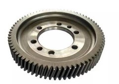
Worm drives inherently rely on sliding friction. Helical gears roll against each other, but worm threads slide aggressively against the wheel. This sliding friction generates immense heat. Heat degrades oil viscosity quickly. You must calculate accurate thermal dissipation rates. Engineers often specify finned housings or synthetic lubricants to prevent catastrophic gear failure.
Many designers assume worm drives provide guaranteed anti-back-drive protection. Self-locking is never guaranteed under external vibration. Adjacent machinery vibration can drastically drop the dynamic friction coefficient. When this happens, the system might back-drive unexpectedly. You must specify dynamic versus static friction coefficients carefully. Always integrate external mechanical braking for safety-critical holding applications.
You face a direct inverse relationship between the reduction ratio and mechanical efficiency. A modest 10:1 reduction might achieve 85% efficiency. Pushing to a 60:1 reduction drops efficiency below 50%. Buyers must accurately model this total power loss. You will likely need to upsize your drive motor to overcome these inherent frictional losses.
You can never run steel against steel in a worm drive configuration. The high sliding friction will cause the metals to gall and seize immediately. You must pair a case-hardened steel worm shaft against a softer gear wheel. Engineers typically use phosphor bronze for the wheel. This bronze acts as a sacrificial wear material. It conforms to the hardened worm profile over time.
Precise gear material specification dictates the lifespan of helical components. Common industry practices utilize robust alloy steels like 8620 or 4340. Heat treatment methods define the final durability. Carburizing provides a hardened outer case to resist wear. The inner core remains ductile to absorb shock loading. Induction hardening offers an alternative for specific localized wear zones.
Heat treatment inherently causes slight material distortion. You must specify post-treatment grinding to correct these microscopic warping issues. Grinding restores the precise involute tooth profile. Achieving a highly polished surface finish minimizes early-stage pitting. Smooth surfaces maintain fluid film integrity much better than rough cut surfaces.
Treating rotating components as completely separate procurement items creates massive risk. Buying them separately leads to inevitable tolerance stacking. The gear pitch line shifts slightly from the intended center. The mesh pattern becomes misaligned during operation. Rapid wear and system failure follow closely behind. You must treat these parts as an integrated mechanical ecosystem.
Each gear type subjects the supporting shafts to unique directional forces. You must select appropriate rotational supports.
Helical applications: These systems generate severe axial thrust. You must specify angular contact bearings or tapered roller bearings. These handle the heavy directional pushing forces effectively.
Worm applications: Worm shafts face extreme separating forces. You must size bearings robustly to absorb these radial and axial loads simultaneously. They must lock the worm shaft firmly in place.
Single-vendor sourcing dramatically reduces your engineering risk. Specifying matched sets ensures perfect mechanical alignment. Sourcing a complete Bearing & Gear assembly simplifies your supply chain. A unified vendor can validate the entire drivetrain tolerances before shipping. This guarantees your components will perform exactly as engineered upon installation.
You must structure your RFQs (Request for Quote) strategically. Ask manufacturers about their tooling availability upfront. Do they possess standard hobs, or do they need custom cutters? This defines your true lead times. Custom tooling adds weeks to your schedule. Standard hobbing keeps prototyping agile and cost-effective.
Never rely on a vendor's verbal quality promises. Insist on documented AGMA (American Gear Manufacturers Association) or ISO quality grades. Higher AGMA numbers indicate tighter machining tolerances. Demand detailed inspection reports for runout, pitch variation, and tooth profile accuracy. Verifiable data protects your operational reliability.
Evaluate vendors based on their willingness to review your application load data. Poor vendors blindly machine parts to a submitted 2D print. Excellent vendors analyze your operating environment first. They catch geometric design flaws before entering production. Collaborative engineering support prevents expensive redesigns and manufacturing delays.
Selecting the right power transmission components dictates your machine's success. Use custom helical gears for maximum efficiency and continuous high-speed motion. Choose custom worm gears to conquer extreme reduction needs and tight space constraints. Always integrate robust bearing supports tailored to the specific thrust profiles of your chosen gears.
Remember, custom specification represents a total system design process. It goes far beyond a simple tooth-profile request. Isolating your gear procurement from your bearing procurement invites mechanical disaster. Tolerance stacking will ruin your machinery.
Take action today to secure your drivetrain reliability. Gather your exact load profiles, operating environment data, and spatial constraints. Submit these critical details to a qualified manufacturing partner for a comprehensive engineering review or an initial RFQ.
A: Lead times depend heavily on tooling availability and material sourcing. Standard industry lead times range from 4 to 12 weeks. Expedited prototyping varies by vendor capacity. If the manufacturer needs to order custom hobs or rare bronze alloys, expect the schedule to extend significantly.
A: Base your choice on efficiency needs versus spatial limits. Bevel gears provide exceptional efficiency because they avoid sliding friction. Worm gears offer massive speed reduction ratios in very confined spaces. Choose bevel setups for continuous power transmission. Choose worm setups when you need high torque reduction.
A: Worm drives generate extreme sliding friction. You cannot run a steel worm against a steel wheel without causing immediate galling. The system has a specific tribological need for a sacrificial, low-friction material. Phosphor bronze combats this sliding wear perfectly while conforming to the steel worm profile.
A: Higher AGMA quality grades increase costs non-linearly. Moving from an AGMA 8 to an AGMA 12 requires specialized grinding and slower machining speeds. You should never over-specify tolerances beyond your actual application needs. Precision costs money. Match the AGMA grade strictly to your operational speed and noise requirements.