 English




Views: 0 Author: Site Editor Publish Time: 11-11-2026 Origin: Site


A hydraulic flange that seeps after reassembly can have a damaged O-ring, mismatched components or a hose that pulls the flange head out of alignment. Extra bolt torque cannot correct those conditions and can damage the joint. A sound installation starts by identifying the exact connection, making the equipment safe to work on and checking that the sealing parts fit together before tightening. Use the equipment and component documentation for the required hardware, torque and commissioning checks. That approach is particularly important when a new hose assembly is being fitted to a port that has already been in service.
Installation overview. Identify the interface, isolate the system and verify release of stored energy, inspect the parts, seat and align the flange, tighten to the specified procedure, and return the equipment to service under the approved commissioning procedure.
A common four-bolt hydraulic flange uses a flange head with a face O-ring and clamps or a one-piece flange to hold it against the port. The hardware applies clamping force, while the O-ring seals at the face. A rectangular four-bolt pattern is a useful identification clue. Confirm the series using the machine documentation, component drawing or exact part number. Check the dimensions and specified hardware against the port before bringing the joint together.
Code 61 and Code 62 are common identifiers for flange families associated with SAE J518 and ISO 6162 configurations. The connection’s size, pattern, flange head and hardware must match the specified series. Nominal hose size does not identify all those features. The words SAE hydraulic flanges identify the product family. Use the exact component drawing and equipment documentation to verify the connection series and service rating for an order.

Part of the joint | What to confirm |
|---|---|
Port and flange head | Series, size, bolt pattern, face geometry, and permitted service conditions. |
Clamp or split clamps | Correct part numbers and fit around the flange head. |
O-ring | Specified size and material, compatible with the hydraulic fluid and temperature. |
Fasteners | Specified thread system, diameter, pitch, length, grade and any washers required by the assembly. |
Installation instructions | Torque, tightening sequence, required thread condition, and the procedure for restoring pressure. |
If the drawing lists fasteners in a different thread system from the loose parts at the bench, resolve the discrepancy before assembly. An incorrect bolt can start in a port thread and still bind or damage it as it goes deeper. Check the port depth and hardware length against the drawing, particularly on replacement equipment with a different port block. A bolt that bottoms in a blind hole can produce a torque reading before the intended clamp load is reached.
Follow the equipment’s approved isolation procedure before opening a hydraulic connection. Secure raised or movable equipment as specified, address accumulators and other stored energy, and verify that the section to be opened has been depressurized. Confirm the condition at the relevant circuit points using the equipment procedure. Trapped pressure can remain in an isolated branch after the pump stops. If the equipment procedure does not establish a safe condition for that branch, resolve it with qualified service personnel before touching the connection.
Once the system is safe to open, keep contamination away from the circuit and protect open ends according to the service instructions. Examine the port face and flange groove for scratches, dents, corrosion and debris. Look at the threads and clamp seating surfaces for signs of previous damage or uneven loading. Clean and inspect the parts using approved materials. Refer damage that crosses the seal contact area, distorted clamps or suspect threads for evaluation under the equipment’s repair criteria.
At a pump, valve or manifold, the port face may be part of a larger assembly. Use the relevant service drawing before deciding whether the damage is repairable or requires a replacement from the pump and valve parts family. A new seal can still leak if the sealing face is scored or the flange head cannot seat squarely. Record what you find at the old seal and port before discarding the parts. A pinched area on the seal, for example, can guide a check for an alignment problem at the replacement joint.
Use the specified seal and any approved assembly lubricant. Seat the O-ring evenly in the groove and check for twisting, pinching or displacement. Bring the head up to the port squarely while supporting the attached pipe or hose. Position the clamps as shown in the assembly drawing. The head should align with the port under the conditions described by the equipment procedure before the fasteners are used to apply clamp load.
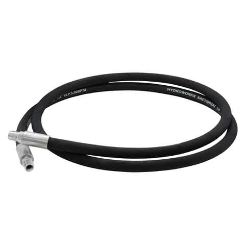
A hydraulic hose assembly can put side load on the head if the hose is twisted, routed too tightly or unsupported. Check the specified bend radius, routing and clamp positions for the installed hose. Confirm that the routing works through the equipment’s range of movement where relevant. A hose that looks relaxed in the parked position can pull on the flange at another point in the travel. Correct the routing under the equipment procedure before tightening the connection.

Where the installation uses rigid pipe, check fit-up against the assembly drawing before using the bolts. A gap or angular mismatch can come from a pipe support or a spool that has moved. Forcing the connection together can load the port and leave the seal unevenly compressed. Address the alignment at the pipe or its support according to the equipment instructions and check that the head stays in position while the clamps are fitted.
Start the specified fasteners by hand and check that they engage smoothly. A bolt that binds needs an inspection of the hardware, alignment or port thread. With the flange aligned, follow the documented tightening sequence and torque for the exact configuration. A staged diagonal sequence is common on four-bolt flanges. Use the sequence, number of passes and final verification method required by the equipment or flange manufacturer.

Use a calibrated torque wrench and verify whether the torque is specified for dry, lubricated or otherwise prepared threads. Thread and seating friction influence the clamp load generated by a torque reading. Use the specified bolts, washers and thread preparation together. If the equipment manual and component instructions appear to conflict, resolve which procedure governs the installed connection before tightening.
Check the flange seating and clamp condition against the manufacturer’s final assembly criteria. Record the component identification, torque specification used and completion of the required checks where the service procedure calls for a record. On equipment with repeated leaks, that record can help identify whether a previous repair changed fastener length, O-ring material or hose routing.
Before commissioning, check that the installed parts match the drawing as a group. Confirm the flange, clamps, bolts and seal against the equipment specification, especially if they were supplied from separate kits. Note any change to hose length, orientation or support. A replacement assembly can have the correct end fittings and still place a different load on the port if its routing changed. For recurring problems, a drawing or service photograph of the approved routing can make that difference easier to identify at the next maintenance interval.
Plan the commissioning check before pressure is restored. The equipment procedure should identify the circuit to be checked, the required sequence and the conditions for returning it to service. Ensure that those performing the check know how to stop the test and re-isolate the equipment if a problem appears. Document the location and circumstances of any leak for the next inspection, including whether it appeared before movement, during operation or after shutdown. That context helps distinguish a fit-up problem from an issue that occurs only when the hose moves.
Restore pressure only through the approved commissioning procedure, with personnel positioned as required and the specified protective measures in place. Check the joint using the approved inspection method and maintain separation from a suspected fluid jet. Never use a hand to locate a hydraulic leak. If there is seepage or other evidence of a fault, shut down, re-isolate and verify pressure release before inspecting or correcting the joint.
Where to look after the connection has been safely isolated again
Observation | Possible causes to investigate |
|---|---|
Seepage starts at one side of the flange face. | Displaced O-ring, damaged seal track or a head that sat at an angle. |
A new seal leaks again after installation. | Wrong seal size or material, damaged groove, distorted head, or hose or pipe loading. |
The fasteners reached torque while the head still appeared out of position. | Incorrect bolt length, a bottomed fastener, mismatched hardware or interference at a clamp. |
Leakage appears after equipment movement. | Hose pull, twist, insufficient routing clearance or a problem at an adjacent joint. |
Fluid can run along a pipe or hose and collect at the flange even when the source is elsewhere. Use the approved leak inspection method to distinguish fluid coming from the seal face from fluid migrating from a nearby component. Follow the equipment’s acceptance criteria before returning the machine to service.
A four-bolt hydraulic flange is ready for commissioning when the specified components match the port, the head seats squarely and the tightening procedure is complete. JOC Machinery lists SAE hydraulic flanges and hydraulic hose assemblies as separate product families. Verify the actual port, flange and hose configuration together when specifying a replacement. If the joint leaks during the approved commissioning check, isolate the system again before looking at seal condition, fit-up and fastener engagement. A service record that captures those checks gives the next technician a concrete starting point if the connection needs attention again.
Use the components specified for the exact flange series and size. Identify the port and hardware from the equipment documents and confirm the matching parts by drawing or part number.
Use the port drawing and verify the diameter and pitch with the appropriate gauge or documented part identification. Confirm the required bolt length and grade at the same time.
Follow the equipment instructions for disturbed seals. Use the specified replacement where required, and confirm size, material and fluid compatibility. A removed O-ring can show compression or damage that affects its ability to reseal.
After safe isolation and pressure release, check the source of the fluid, groove and face condition, part compatibility, alignment and bolt engagement. Review hose or pipe loading and the documented tightening procedure before commissioning again.