 English



Views: 0 Author: Site Editor Publish Time: 16-09-2026 Origin: Site


High-pressure hydraulic systems rely on exact fluid regulation. This dynamic makes the adjustable screw a critical point of failure or success. A poorly specified screw quickly leads to pressure drift. It can trigger hidden internal leakage. In extreme cases, you might face catastrophic valve failure. Moving from prototype to production demands careful planning. You must translate raw engineering intent into precise manufacturability standards. Vague specifications simply will not work in fluid power applications. To successfully source a CNC machining adjustable screw, procurement and engineering teams must align closely. They need well-defined material limits. They must enforce exact dimensional tolerances. They must also execute strict supplier verification methods. Following this structured approach ensures long-term system reliability. It prevents unexpected downtime in the field.
Material selection dictates lifespan: Match stainless steel CNC machining or brass CNC machining to the specific fluid type and system pressure limits.
Thread precision and surface finish (Ra) are non-negotiable for O-ring sealing and anti-galling.
Evaluating a manufacturing partner requires verifying their deburring processes, CMM inspection capabilities, and ISO compliance for hydraulic valve parts.
Over-tolerancing drives up costs; applying strict tolerances only to critical sealing and mating surfaces ensures scalable production.
Adjustable screws operate inside relief, flow control, and pressure-reducing valves. They face a unique mechanical challenge. They must maintain exact static positions. They do this under severe dynamic loads. These hydraulic pressures often exceed 3,000 to 5,000 PSI. The screw holds back massive fluid force. Any structural weakness compromises the entire valve block.
Failure brings severe operational risks. Thread galling frequently occurs during routine field adjustments. This locks the screw permanently in place. Poor surface finishes create pathways for micro-leaks. High-velocity fluid escaping through these leaks generates localized heat. This heat degrades O-rings rapidly. System vibration also causes loose screws to back out over time. This gradually alters the pressure setting.
We define engineering success through strict performance metrics. Actuation must remain completely smooth. The O-ring gland must deliver zero-leakage sealing. Torque requirements should feel predictable during maintenance. You must also ensure zero particulate contamination. Microscopic machining burrs easily detach inside the valve. Stray metal destroys downstream actuators instantly.
Engineers often design for the nominal operating pressure. They forget about momentary system shocks. A system rated for 3,000 PSI might experience 5,000 PSI spikes. These spikes deform weak adjusters. You must establish success criteria based on the absolute peak pressure. You should also define the required adjustment frequency. Screws adjusted daily need much harder contact surfaces than set-and-forget components.
Choosing the right material prevents early component failure. You must balance mechanical strength against fluid chemistry. Certain fluids strip away protective platings. Others cause rapid corrosion in raw steel. Matching the alloy to the environment is your first major design decision.
Material Category | Common Alloys | Primary Application | Key Trade-offs |
|---|---|---|---|
Stainless Steel | 304, 316, 416, 17-4 PH | Corrosive environments, water-glycol fluids | Higher machining costs; galling risks require heat treatment. |
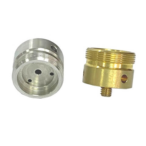
Brass Alloys | C36000, C35300 | Low-pressure systems, pneumatic crossovers | Excellent machinability; deforms under high torque spikes. |
Carbon Steels | 12L14, 4140 | High-strength requirements, petroleum oils | Requires post-machining platings to prevent rust. |
Stainless steel dominates demanding applications. We typically use 304 or 316 for standard corrosive environments. We shift to 416 or 17-4 PH when extreme hardness matters. These harder alloys handle water-glycol fluids effortlessly. However, they present distinct trade-offs. They accelerate tool wear during machining. They also suffer from thread galling. You must specify specific heat treatments to prevent threads from welding together under load.
Brass provides a highly efficient alternative. Free-machining brass cuts perfectly. It suits low-to-medium pressure systems well. You often see it in pneumatic crossovers. Standard petroleum-based hydraulic oils show excellent compatibility. Machining brass lowers your per-part price significantly. Yet, it carries structural limits. Extreme torque easily shears brass threads. High-pressure spikes can deform the sealing tip.
Carbon steels offer massive tensile strength. Engineers rely on 12L14 or 4140 for heavy-duty industrial valves. These metals handle shock loads perfectly. Corrosion remains their primary weakness. System fluids sometimes manage this rust risk. More often, you need post-machining platings. Zinc-nickel plating provides excellent protection. You must account for this plating thickness in your initial thread design.
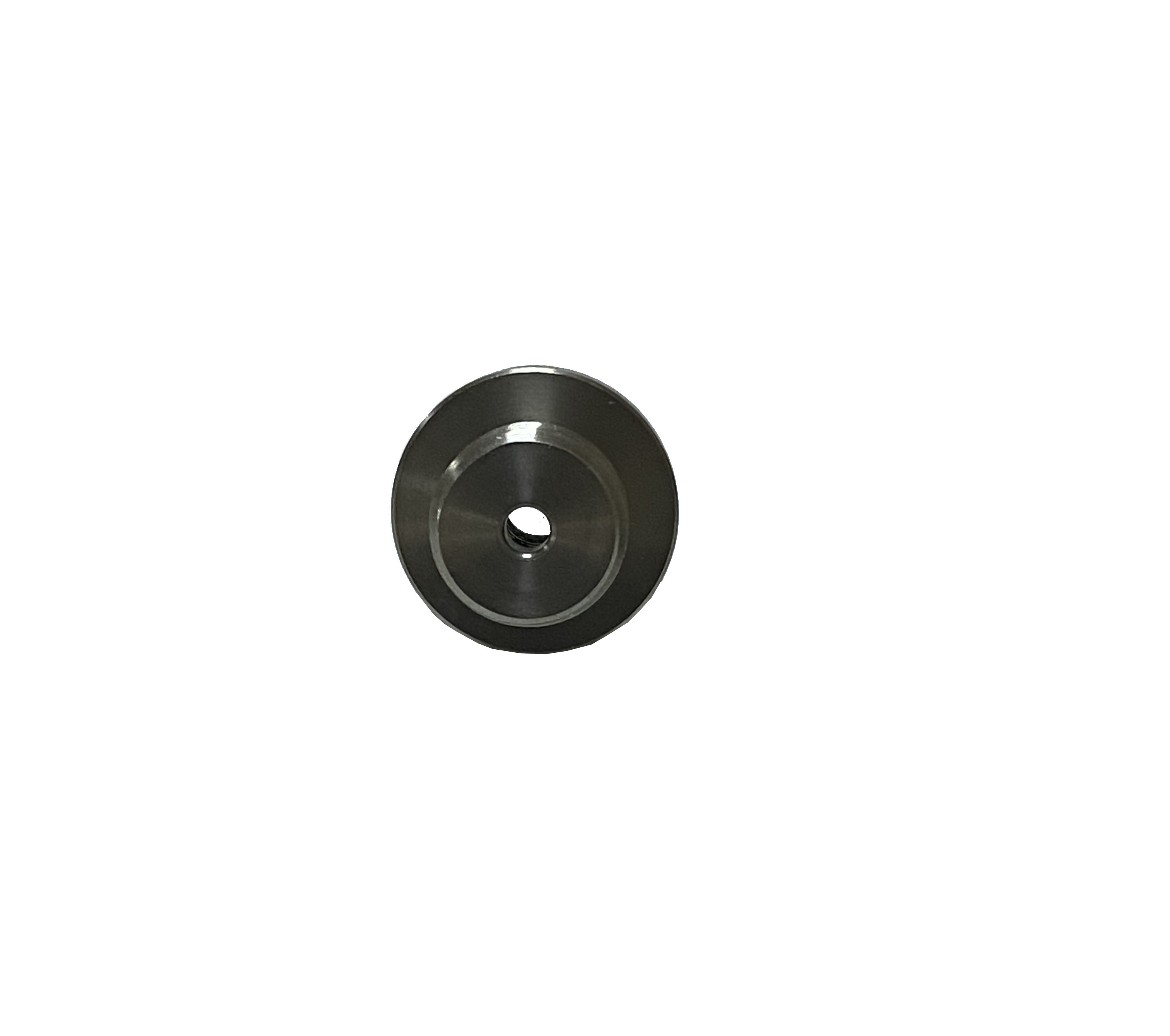
Standard fasteners cannot handle fluid power applications. Specifying a precision adjustable screw requires strict dimensional control. Every micron matters. A slight deviation in thread pitch allows fluid bypass. A rough sealing surface shreds expensive O-rings. We strictly control four dimensional categories.
Thread Fit and Classification: Standard Class 2 fits fail under pressure. They allow too much movement. Specify Class 3A/3B threads instead. This tighter fit prevents high-pressure fluid bypass. It also provides crucial friction. This friction stops vibration from loosening the screw.
Concentricity and Runout: The thread axis must align perfectly with the sealing tip. This applies whether you use a needle tip or a flat face. Perfect concentricity ensures even seating against the valve body. Typical runout tolerances must remain under 0.001 inches. This equals 0.025 millimeters. Off-center tips create permanent leak paths.
Surface Finish (Ra) at the Sealing Gland: O-ring grooves demand extreme smoothness. Dynamic sealing surfaces rub against rubber constantly. Require a fine finish of 16 Ra or better. Rougher surfaces act like sandpaper. They cause severe seal abrasion during routine adjustments.
Heat Treatment & Plating: Hardness prevents wear on the adjustment tip. Specify exact Rockwell hardness (HRC) requirements. Plating requires equal attention. Plating adds physical thickness to the part. You must specify exact plating thickness allowances. Failure to do so causes post-plating thread binding.
Do not guess your Ra requirements. Call out the finish explicitly on the drawing. Machine shops cannot read minds. They might turn the part quickly to save cycle time. This leaves microscopic feed lines. These lines guarantee fluid leaks. Specify polishing or burnishing for critical glands if turning cannot hit 16 Ra.
Not all job shops can handle hydraulic components. Evaluating partners takes specific logic. You need shops familiar with high-pressure demands. Sourcing a bracket differs entirely from sourcing a pressure-retaining valve adjuster. When sourcing custom CNC parts, look for specialized expertise.
Vendor Shortlisting Logic: Reject shops without fluid-power machining experience. Ask about their hydraulic portfolio. They must understand why a microscopic scratch matters. General job shops rarely grasp this zero-leakage mentality.
Deburring Capabilities: Intersecting holes create burrs. Thread runouts leave sharp edges. These areas require 100% burr-free results under magnification. Shops must use thermal, electrochemical, or dedicated microscopic hand deburring. Stray metal shavings will destroy hydraulic pumps.
Inspection and Quality Control (QMS): Require a robust Quality Management System. Ask for first-article inspection (FAI) reports. Demand automated CMM reporting for complex geometries. Require material test reports (MTRs). Full traceability protects you from counterfeit alloys.
Tooling & Machine Rigidity: Verify the equipment used. Small-diameter, long screws deflect under cutting pressure. Look for Swiss-type CNC lathes. Swiss machines support the workpiece continuously near the cutting tool. They maintain tight geometric tolerances effortlessly.
Ask potential suppliers about their scrap rates on Class 3 threads. Honest shops will explain their tool monitoring processes. They change inserts before threads go out of tolerance. Poor shops wait for the thread gauge to fail before reacting. Proactive tool management separates reliable partners from risky ones.
Design choices dictate manufacturing prices directly. Small drawing changes often double production expenses. Design for Manufacturability (DFM) eliminates these hidden traps. Engineering teams must review prints strictly before issuing quote requests.
The over-tolerancing trap ruins budgets frequently. Engineers sometimes apply tight tolerances to every dimension. They lock down non-critical areas. Exterior drive slots do not need extreme precision. The hex head does not need a 0.001-inch tolerance. Tightening these general dimensions inflates cycle times. It forces the shop to slow down. It dramatically increases scrap rates. Apply strict limits only to sealing and mating surfaces.
Standardizing threads saves massive amounts of time. Designing custom thread pitches seems innovative. In reality, it causes supply chain nightmares. Custom pitches require custom cutting tools. Shops must special-order these tools. This increases your lead times. It also raises your setup fees. Always utilize standard UNF or Metric fine threads. Standard tooling sits on every machine shop shelf.
Consolidating operations changes the pricing math entirely. Design the screw for single-setup machining. Industry experts call this "done-in-one" production. A part that finishes entirely on a mill-turn machine costs less. Moving a part between different machines requires secondary handling. Secondary handling introduces human error. It causes chuck marks. It ruins concentricity. Eliminating secondary steps reduces your cost per part.
Specifying the right adjustable screw requires a rigorous engineering approach. You must balance material science against environmental realities. You must control thread geometry flawlessly. You must demand superior surface finishing. Even tiny design oversights trigger massive hydraulic failures. Precision truly matters at high pressures.
Take direct action before issuing an RFQ. Review your technical drawing thoroughly. Clearly demarcate critical sealing tolerances from general, non-functional dimensions. Verify your thread classes. Confirm your Ra callouts. A clean, explicit drawing guarantees accurate supplier quotes.
Do not leave manufacturability to chance. Contact our engineering team today. We provide thorough manufacturability reviews for your hydraulic valve components. We spot DFM traps early. We ensure precision, production scalability, and highly predictable manufacturing costs.
A: Dynamic seals typically require a surface finish of 16 Ra microinches (0.4 micrometers) or better. This extremely smooth surface is vital. It prevents premature seal wear. It stops rubber abrasion during routine field adjustments under pressure.
A: Specify dissimilar hardness levels between the screw and the valve body. You can also utilize specific high-pressure thread lubricants. Alternatively, specify anti-galling treatments. Passivating the stainless steel helps. Specialized platings like silver or proprietary anti-galling coatings also eliminate this issue.
A: Swiss-type lathes support the workpiece continuously near the cutting tool. This prevents metal deflection during machining. This rigidity is crucial for long, slender adjustable screws. It perfectly maintains high concentricity between the drive head and the sealing tip.
A: Always request Material Test Reports (MTRs) to verify exact alloy composition. Demand First Article Inspection (FAI) reports for strict dimensional verification. Finally, require certificates of conformance (CoC) for any external heat treating or post-machining plating processes.